Tiny Titan "supercomputer" uses blink(1) USB LEDs

This is so neat! A few years ago, the Oak Ridge National Lab created "Tiny Titan", a demonstration of how supercomptuers work using a cluster of Raspberry Pis. It's a scaled down model of the Titan supercomputer. To visualize what each note of the cluster is doing, blink(1) USB LEDs are plugged into each Raspberry Pi, indicating what its up to.

More details from this Popular Science article and the Tiny Titan homepage.  Or create your own (since it's all open source) by visiting the TinyTitan github repo at https://github.com/TinyTitan.

(photos courtesy of reddit user "0110010001100010" in this post)

Using the blink(1) mk2 LED strip adapter

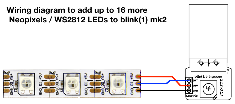
Now you can more easily add "Neopixel" WS2812 LED strips to your blink(1) mk2 with the "blink1 LED strip adapter". This is a simple PCB that breaks out the tiny 3-pin socket on the blink(1) board to a standard 0.1" spacing for LED strips. The design is completely open source and you can get your own made for a few bucks by going to the blink1-ws2812-adapter page on OSHPark.

Below are some photos showing how you can solder one up to a blink(1) mk2 circuit board. It assumes you've already taken the board out of the enclosure as described in a previous post.

Gathering parts

Here's all the parts you need:

  • blink(1) mk2
  • blink1-ws2812-adapter board
  • 8-pin stacky header or equivalent

The tools you will need are the standard kit for electronics work:

  • soldering iron & solder
  • needle nose pliers
  • diagonal cutters
  • locking tweezers or small clamp

Aligning the boards

After removing the blink(1) circuit board from its enclosure,  we need to get three sturdy "wires" to go from the blink(1) to the adapter board. I like using the pins of a "stacky header". To remove them, just pull them out with needle nose pliers.

Then, line up the blink(1) and the adapter board and insert the three pins.  It's handy to have a clamp or auto-closing tweezers to hold the two boards together while you're doing this.

Soldering the boards together

And now just solder from the top and from the bottom, taking care not to bridge solder across the pins.

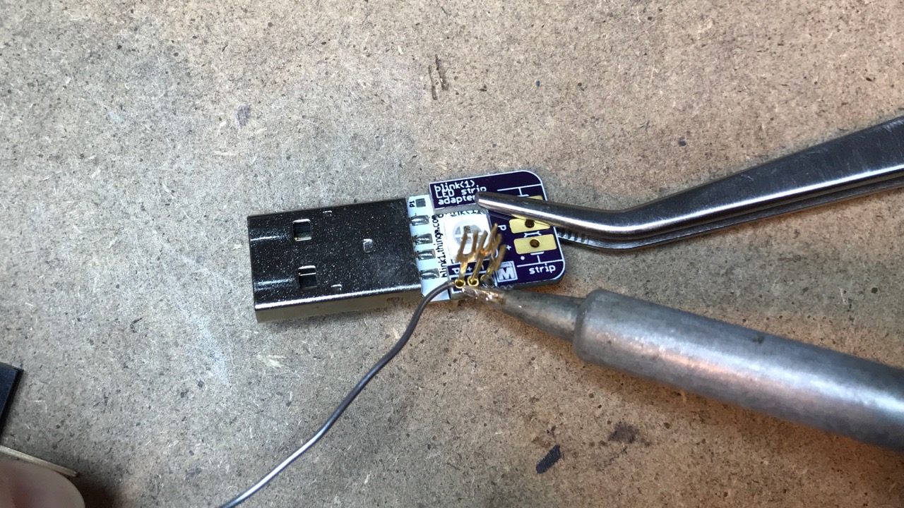
Finally trim the pins/wires close to the boards. Trim one lead at a time to prevent possible shorting. And do a quick continuity check afterwards to make sure nothing in shorted.

Adding the LED strip header socket (optional)

You can also solder in a female header socket to make it easy to add and remove LED strips. Using the remaining part of the "stacky header", pull out another pin and cut the header to leave you with a 3-pin header socket.  Insert that into the adapter board, solder it down, and trim the excess leads.

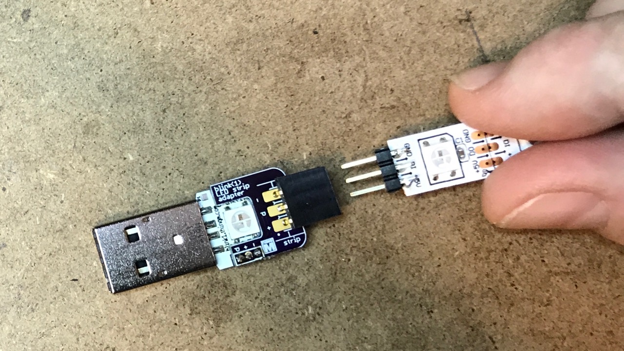
Plugging in LED strips

Now you can plug in strips. If you solder a 3-pin header onto your strips, you can plug them in straight away! Be sure your strip matches the order of "GND-DAT-5V" for the connections. Most strips have this, but some don't. Otherwise, you can solder wires onto the strips and them plug them into the socket.

Controlling the LEDs

With the 'blink1-tool' command-line program (available from the blink1 project releases page), you can use the 'ledn' parameter to set which LED you'd like to control. When 'ledn' is zero, all LEDs are changed. LED 1 and 2 are the top and bottom LEDs of the blink(1), respectively.

blink1-tool --ledn 5 --rgb '#FF00FF' // turn 5th LED purple

blink1-tool --led 16 --random=100 -m 10 -t 10 // party mode!

Blink1Control2 v2.0.4 released

Blink1Control2 v2.0.4 has been released and it fixes several issues.  Please update to take advantage of the fixes.  Blink1Control2 is the official desktop application for controlling blink(1) USB LEDs and connecting them to the Internet. You can find builds for

blink1control2-beta-screenshotIf you are unfamiliar with Blink1Control2 compared to its predecessor, here is a quick video run-through of how Blink1Control2 works:

And if you run into any problems, please don' hesitate to open an issue on the Blink1Control2 issues page.

Adding NeoPixels / WS2812 LEDs to blink(1)

[originally posted on todbot blog] You may not have known, but blink(1) USB notification LEDs have a secret: they can drive 16 extra LEDs in the form of "NeoPixel" WS2812 LEDs.  This is what was behind the "blink(16)" project.

If you take apart a blink(1), you'll see it has three tiny plated holes. These are the three needed by WS2812 LEDs: +5V, Gnd, and Data.

Or, in diagram form against a standard WS2812B strip:

Taking apart a blink(1) to wire it up for extra LEDs isn't too difficult if you're okay with a bit of soldering.  Here's videos showing two different ways to do it:

blink(1) is OSHWA-certified Open Source Hardware!

We are very happy to announce that our blink(1) USB RGB LED is one of the first pieces of hardware to be part of the OSHWA Open Source Hardware Certification program.  The OSHWA UID for blink(1) is US000051. We believe in open hardware and strive to make blink(1) as open as possible. ThingM is also a supporting corporate member of OSHWA. To see blink(1) sources and design files, visit the blink(1) github.

You can see a list of all current OSHWA-certified devices here and see the requirements for certification here.  We feel honored to be included with other great hardware makers, like those listed below.


Neat German article on using blink(1) with Raspberry Pi

The website Electrkonik Kompendium has created a detailed set of articles on installing and using  blink(1) on a Raspberry Pi.  They go through compiling the tools, using them to play around, and then hooking blink(1) to display system services status or user login state via cron.  Even though it's in German, it's pretty readable via automatic translation.


Tod speaks at Hackaday Superconf about Blink1Control2

In November 2016, I (Tod) was fortunate enough to speak at the Hackaday Superconference. It was an incredible conference, one of the best I've been to.  For ThingM, I've mostly been working on software lately, getting Blink1Control2 to a usable state, so speaking at a hardware conference was a bit daunting.  But I do consider blink(1) to be an "Internet of Things" device, even though it's tethered to a computer. ThingM was created as a ubiquitous computing  design studio, essentially an IoT company before IoT.  In my talk I propose using the much richer computer GUIs to configure IoT devices, and one way I've been liking making computer GUIs is what I've been using for Blink1Control2: Node.js and Electron.

Mike at Hackaday did a great writeup of my talk and the video of it is below. (I can tell I'm out of practice giving talks after having my head down in code for over a year now :-)

Announcing Blink1Control2: public beta

In late 2015, we started looking to update our Blink1Control GUI application for blink(1). The app has some strange UI choices, acts oddly on certain systems, and is hard to maintain. We started again looking for a solution to the problem we've tried to solve twice before: how to create a single cross-platform application that works well on every platform (including Linux). The app must integrate nicely with hardware and networking, have strong open-source backing, and can be maintained by a small staff (like one person, me). It turns out there's not a lot of solutions to this laundry list of desires. But we think Electron (the app framework created by GitHub and behind Atom and Slack) looks like a good choice. So for the last several months, Blink1Control2 has been in development and testing.

With that, here is the first public beta of Blink1Control2.

blink1control2-beta-screenshot

New features in Blink1Control2

  • Multiple blink(1) support
  • Skype support
  • Redesigned "Event Sources" UI to more easily manage multiple ways to trigger blink(1)
  • Greatly improved File/URL/Script support
  • New "meta-patterns" for on-the-fly creation of color patterns
  • Redesigned UI that looks great on HighDPI/Retina systems
  • So many many bugfixes
  • New bugs we haven't found yet

Features not yet in Blink1Control2

  • Battery / CPU / Network level checking
  • POP email support
  • Certain API server calls

Blink1Control2 is written in Node.js and Electron. Electron is an amazing open source system created by Github for using web technologies to write desktop apps. Its most famous example is the Atom text editor.

We're very excited about the new Blink1Control2. One of the design changes was to make the "Event Sources" modular, so new event sources could be added easily. We're not there yet, but we're getting very close. If you have an idea of a neat event source we should add, let me know!

As with all things blink(1), Blink1Control2 is entirely open source.

Here's a screencast showing basic use of Blink1Control2 and goes over some of its features.

Downloads:

  1. Windows Installer - Blink1Control2.Setup.2.0.0-beta3-win32-x64.exe
  2. Windows Zip file - Blink1Control2-2.0.0-beta3-win32-x64.zip
  3. Mac DMG - Blink1Control2-2.0.0-beta3-mac.dmg
  4. Mac Zip file - Blink1Control2-2.0.0-beta3-mac.zip

Some useful links: - Main development page: https://github.com/todbot/Blink1Control2 - Releases: https://github.com/todbot/Blink1Control2/releases - Issues/Bugs: https://github.com/todbot/Blink1Control2/issues

Learn Twitter Node API with "twitter-streaming-blink1"

twitter-streaming-blink1 Twitter has a great API for searching through tweets. But it can also be a bit daunting if you've never interfaced with APIs before. In the Node.js universe, there's a great package called "twit" that makes it really easy to use the Twitter API. And what better way to show off your Twitter API knowledge than to hook it up to a blink(1) light, which is just what @jbulava did with "twitter-streaming-blink1". The code is a single well-commented file that needs only a few lines of code to do searches and acting on tweets.

Look how succinct it is: